Zehnder ComfoAir E300 HA Integration
It started with a simple search for a Home Assistant integration for my Zehnder ComfoAir E300. I quickly found that most projects were limited to basic 3-way switch overrides. At some point I stumbled upon this thread hinting at a deeper interface.
At the time, I’d lent out my multimeter, so I couldn’t do much investigation. I followed the thread and waited. Then about two weeks ago, @CodedCactus made progress and started work on an ESPHome component, which was the spark I needed.
The Hardware Hunt
I wasted no time ordering an RS485 to TTL module to pair with an ESP32 I had lying around.
Once the module arrived, I did some quick soldering and used a standard network cable to connect the RS485 module to the Zehnder’s C3 port.
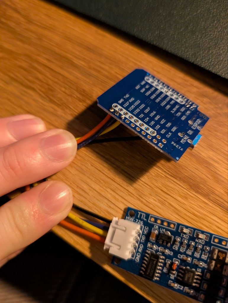 Drafting the physical connection.
Discovery and Collaboration
The initial register set was small. Without other scanning tools, I started by cloning @CodedCactus’s work to investigate further. I found a minor bug when the outside temperature dropped below zero (which I reported in PR #1) and eventually identified several missing registers while tinkering with the unit’s settings (PR #2).
It’s been great collaborating on this, especially since @CodedCactus is doing most of the heavy lifting on the ESPHome component—this project definitely wouldn’t be where it is without his dedication.
The Case (Iteration 1)
With things working, I fired up OpenSCAD and designed a 3D-printed enclosure. I was a bit lazy and used the listed dimensions for the components rather than measuring them myself.
When I pulled it off the printer, the realization hit: it didn’t fit. The connector stuck out too far.
 The “specs vs reality” moment.
I grabbed my trusty calipers, measured the actual modules, and printed version 2. this time it fit perfectly :).
The Pivot to 0-10V
I wanted control, not just data. Unfortunately, it seemed the discovered RS485 registers were read-only. I looked toward the Zehnder’s 0-10V interface as an alternative.
I found the DFRobot GP8211S DAC module and connected it to the ESP32.
To make this work the following needs to be appended to the ESPHome config:
ESPHome Config
i2c:
  - id: bus_a
    sda: GPIO23
    scl: GPIO22
    scan: true

gp8403:
  id: gp8211
  voltage: 10V
  model: GP8413
  i2c_id: bus_a

output:
  - platform: gp8403
    id: gp8211_output_1
    gp8403_id: gp8211
    channel: 0

number:
  - platform: template
    name: "GP8211 Voltage Control"
    id: gp8211_slider
    min_value: 0
    max_value: 10
    step: 0.1
    unit_of_measurement: "V"
    initial_value: 0
    optimistic: true
    set_action:
      then:
        - output.set_level:
            id: gp8211_output_1
            # We divide by 10 because set_level expects a value from 0.0 to 1.0
            level: !lambda 'return x / 10.0;'
“Winging it” and Final Calibration
Still without my multimeter, I decided to “wing it” and connect the DAC to the unit. It worked, but setting it to 10V only registered as 9.2V on the Zehnder. After digging into the unit’s settings, I found the Analoog 0-10V Max. Instelling and adjusted it to match the actual output.
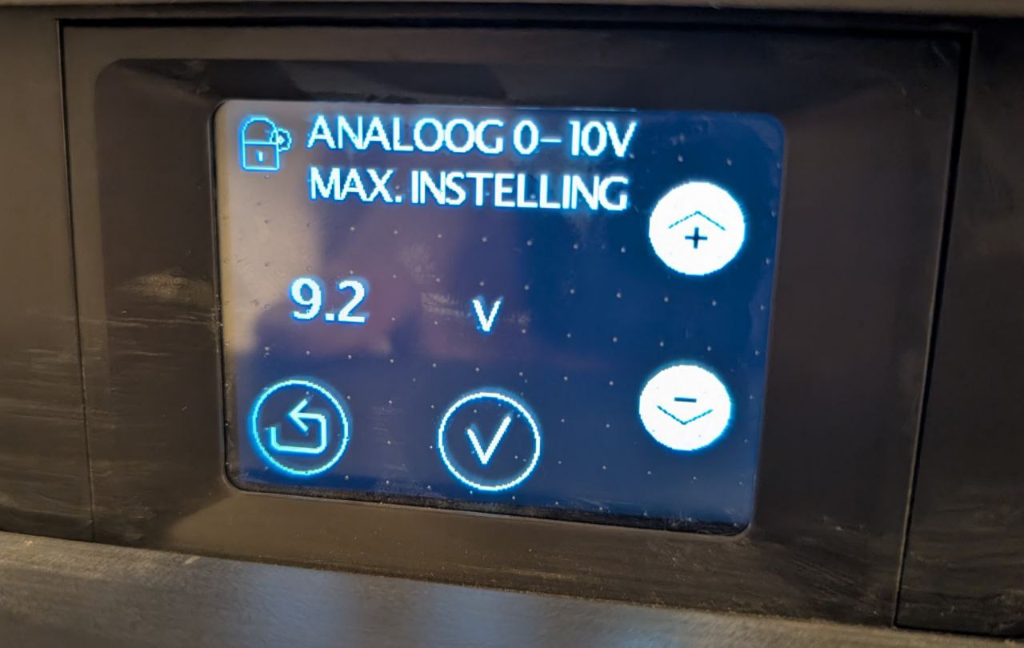 Adjusting the maximum voltage setting to calibrate the DAC.
I also changed the Analoog 0-10V Methode to Proportioneel Debiet. This allows fine-grained ventilation control based on the input voltage, rather than just mapping to the three standard presets.
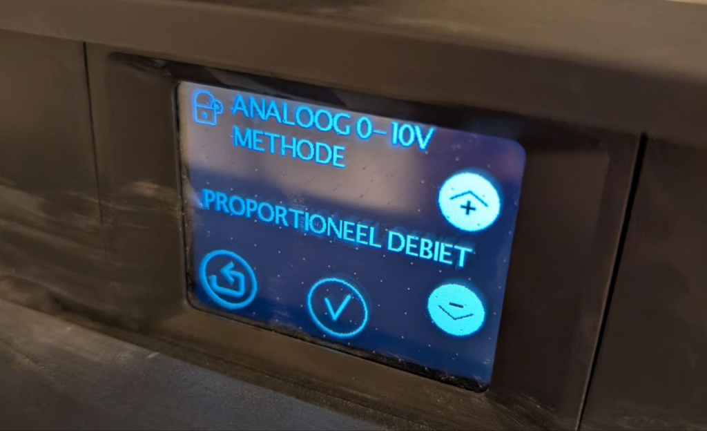 Setting the unit to proportional flow mode.
The Enclosure (OpenSCAD)
To house the final assembly, I continued refining the previous OpenSCAD design. The benefit of a parametric script meant I could simply expand the dimensions and add cutouts for the new DAC module without starting from scratch.
I’ve uploaded the final parametric design to Printables for anyone looking to print their own. You can find the model right here: ComfoAir E300/400 ESPHome Unit.
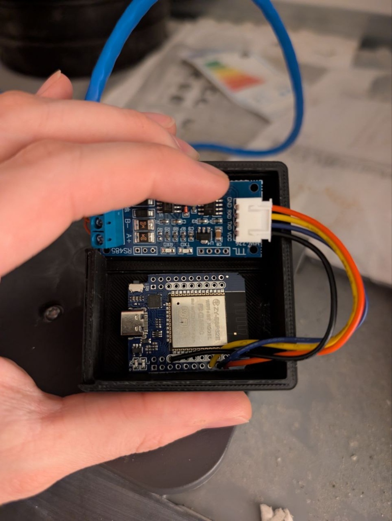
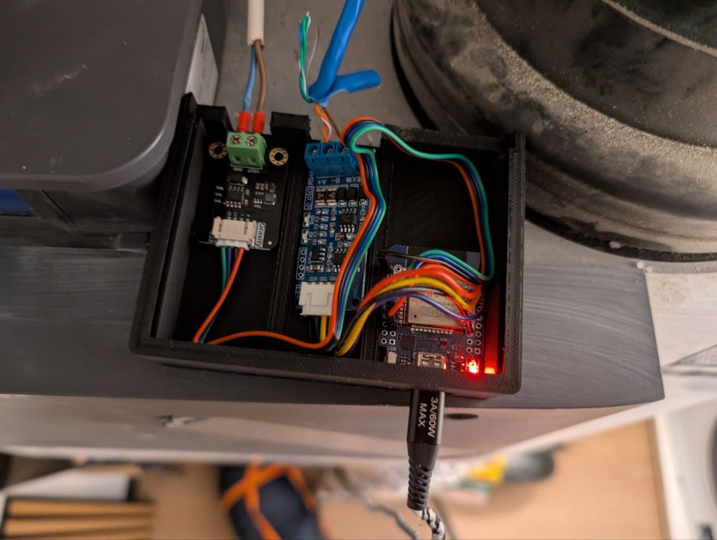 Revision 2 of the OpenSCAD case, now housing both the RS485 and the DAC.
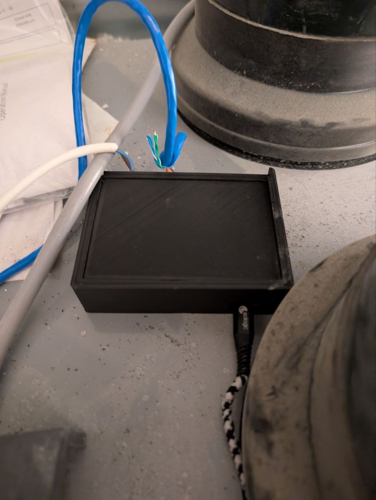 Closed up and in service.
Pin Mapping
Here is a clear breakdown of the wiring between the ESP32 Mini D1, the modules, and the Zehnder unit itself.
ESP32 to Modules
| Component | Pin | ESP32 Pin | Function |
|---|---|---|---|
| RS485 to TTL | VCC | VCC (5V) | Power |
| GND | GND | Ground | |
| RXD | IO25 | Data Receive | |
| TXD | IO27 | Data Transmit | |
| GP8211S DAC | + (VCC) | 3V3 | Power |
| - (GND) | GND | Ground | |
| D (SDA) | IO23 | I2C Data | |
| C (SCL) | IO22 | I2C Clock |
Modules to Zehnder Unit
| Module | Terminal | Zehnder Port | Function |
|---|---|---|---|
| RS485 | A | C3 - A+ | RS485 Data+ |
| B | C3 - B- | RS485 Data- | |
| GND | C3 - GND | RS485 Ground | |
| GP8211S DAC | VOUT | C1 - 0-10V | Control Signal |
| GND | C1 - GND | Signal Ground |
The Result
I now have access to the sensor data and, more importantly, the ability to ramp up ventilation automatically when we’re showering or when CO2 levels rise. All that rests is a final cleanup of the cables and maybe dust off the unit :).
Bill of Materials
- ESP32 Mini D1
- RS485 to TTL Module
- DFRobot GP8211S DAC Module
- 3D Printed Enclosure
- Standard RJ45 Network Cable (for the C3 connection)
Join the Effort
The work is far from finished. We are still actively mapping more registers to unlock even more data and control possibilities.
If you own a Zehnder ComfoAir unit and have discovered something new, or if you’re interested in testing, your input would be invaluable. Check out the ESPHome component repository and help us make this integration even better for everyone.